| Fiber
Couplers and Collimators (PAF FiberPorts) |
Intro
The OFR FiberPort (US Patent 5,638, 472) is an ultra-stable, miniature micropositioner, enabling active alignment of an AR-coated OFR aspheric lens for collimating or for free beam-to-fiber coupling. FiberPorts serve both input and output funtions, and are micro-positionable in six degrees of freedom: 3 linear (x, y, z) 2 angular (azimuth, elevation) 1 rotational (for PM fiber alignment). While performing the same functions as large benchtop 5-axis positioners, the compact size of the Fiber-Port makes it ideally suited for incorporating into shipable OEM equipment, as well as for utility in the development laboratory. A major application for the FiberPort among many laser manufacturers is as the laser interface to an output fiber pigtail. See page FO-39 for suggested means of mounting a FiberPort to a laser. Final alignment is done on site following simple instructions furnished by OFR. It is the FiberPort’s rugged construction, stability and coupling efficiency that make it popular for this application. The FiberPort is characterized by ultra-stability. Once aligned to maximum coupling efficiency, there is no drift, in spite of temperature changes, shock and vibration beyond that experienced in the normal laboratory.
Which fiber? How is it connected?
FiberPorts are available for single-mode (SM), polarization-maintaining (PM) and multimode (MM) fibers. FiberPorts, which mate to detachable, connectorized fibers, are available with FC receptacle (X-Type and XM-Type) or SMA receptacle (SMA-Type). The micro-aspheric Lens in the Fiber-Port is AR coated. Specify wave-
length when ordering. For a description of the micro-aspheric Lenses, see Coupling Lenses, page FO-15.
| Fiber Type |
FiberPort |
Receptacle |
Description |
| SM or PM |
X-Version |
FC |
For FC connectorized fiber |
| SM or PM |
H-Version |
none |
Non-detachable pigtail |
| MM |
XM-Version |
FC |
For FC connectorized fiber 50µm, 62.5µm, 100µm |
| MM |
SMA-Version |
SMA |
For SMA connectorized fiber 50 - 600µm |
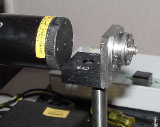
PAFmounted on HCP
|
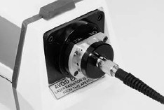
PAF mounted to laser using HCC adaptor |
|
Wavelength
Range (-5, -8, -11) |
Order as |
| 450 - 600 nm |
VIS |
| 550 - 750 nm |
VIR |
| 750 - 960 nm |
NIR |
| 960 - 1100 nm |
YAG |
| 1275 - 1600 nm |
IR |
| 1480 - 1600 nm |
IR2 |
|
Click here for FiberPort
Alignment Instructions |
|
PAF FiberPorts |
|
Beam |
Beam Diameter |
Singlemode # |
Multimode # |
Connector Type |
|
|
0.5 mm |
PAF-X-2 |
----- |
FC |
|
|
1.0 mm |
PAF-X-5 |
----- |
FC |
|
|
1.6 mm |
PAF-X-7 |
----- |
FC |
|
|
2.0 mm |
----- |
PAF-XM-5 |
FC |
|
|
2.0 mm |
----- |
PAF-SMA-5 |
SMA |
|
|
2.4 mm |
PAF-X-11 |
----- |
FC |
|
|
3.4 mm |
PAF-X-15 |
PAF-XM-7 |
FC |
|
|
3.4 mm |
----- |
PAF-SMA-7 |
SMA |
|
|
4.9 mm |
----- |
PAF-XM-11 |
FC |
|
|
4.9 mm |
----- |
PAF-SMA-11 |
SMA |
(Ordering info)
FiberPort for Single-Mode & Polarization-Maintaining Fibers
OFR X-Type FiberPorts use an FC receptacle for FC-connectorized fibers. For applications requiring non-detachable fiber pigtail, H-Type FiberPorts are also available.
The fiber connecting to a FiberPort terminates in air. To minimize the effects of the resultant back reflection, an FC/APC angle-polished connector is used. On the other hand, with an FC/PC connector or a straight polished connector, there is a -14 dB return loss. OFR FiberCables are available in standard FC/APC or optional FC/PC.
Launching a Free-Beam into PM Fiber
It is critical that fiber and laser polarization axes be aligned when launching into a PM fiber. This task is made much easier if a 1/2-Wave Retarder is inserted into the beam. A FiberBench solution is recommended, with rotatable zero-order 1/2-Wave Retarder for rotation of polarization plane, mounted onto the FiberBench base. Alignment is then a straightforward procedure.
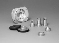
Interchangeable FiberPort Lenses and Replacement Bulkheads
Normally, the only difference between FiberPorts used in different applications is the lens focal length, usually determined by the application. All FiberPort Lenses are mounted in a Cell that is compatible with all FiberPort models. The Cell positions the principal plane of the Lens at one focal length distance from the polished fiber endface, resulting in collimation. FiberPort Lens Cells are magnetic, and are easily installed and interchanged on site.
Thus, for experimentation purposes, rather than interchanging FiberPorts (containing different focal length lenses), it is more economical to interchange Lenses, mounted in their magnetic Cell, using a single FiberPort.
Bulkhead requirement.
The Bulkhead, the threaded portion on which the Connector attaches, is different in length for the two groups of Lenses as listed below.
FiberPort Lenses LLO-PAF-2,5,7 can be interchanged using FCBH-S Bulkhead. Likewise, LLO-PAF-11,15 use the FCBH-LA. When interchanging Lenses from one group to another, it is not necessary to change FiberPort bodies. It is only necessary to interchange Bulkheads. In summary, interchanging Lenses and Bulkheads is simple, quick and economical.
FiberPort Lens Cells |
|
Catalog
Number |
Effective
Focal Length |
| LLO-PAF-2-λ |
2.0 mm |
| LLO-PAF-5-λ |
4.6 mm |
| LLO-PAF-7-λ |
7.5 mm |
| LLO-PAF-11-λ |
11.0 mm |
| LLO-PAF-15-λ |
15.4 mm |
| λ: Specify wavelength in nm and use coating code NIR, YAG, IR etc... |
Bulkheads |
Order |
Description |
| FCBH-S: |
short bulkhead with tungsten insert (-2-,5,-7) |
| FCBH-SA: |
NEW short angled bulkhead with tungsten insert (-2-,5,-7) |
| FCBH-L: |
long straight bulkhead with tungsten insert (-11, -15, -18) |
| FCBH-LA: |
long angled bulkhead with tungsten insert (-11,-15, -18) |
| SMA-C: |
CSMA bulkhead (-5,-8), original |
| SMA-S: |
short SMA bulkhead (-7) |
| SMA-L: |
long SMA bulkhead (-11) |

|