The FiberPort is a 5-axis fiber collimator and coupler. It uses a moveable lens as the alignment mechanism while holding the fiber stationary. This provides an extremely stable and repeatable platform for coupling and collimating.
DESCRIPTION
Figure 1 shows the FiberPort. The components of the FiberPort are the bulkhead, the clamp plate, the FiberPort body with internal components, and the tilt plate (not seen).
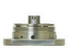
Figure 1.
The bulkhead is locked onto the FiberPort by the clamp plate and the clamp plate screws. Inside the FiberPort body is a magnetic cell containing a lens. This magnetic cell adheres to the tilt plate inside the FiberPort body.
Inside the FiberPort, the lens cell floats on a leaf spring. The leaf spring provides the X-Y motion of the lens cell (see next section for details). The Z/ q / j (tip, tilt, yaw) motion of the lens is controlled by three socket head cap screws (SCHS) in combination with plunge screws. The plunge screws provide a counterforce to the SCHS which push against the tilt plate and control the Z/ q / j motion of the lens.
MECHANISM OF THE FIBERPORT
The FiberPort is adjustable in X-Y and Z/ q / j (tip, tilt, yaw). All adjustments of the FiberPort are coupled. The lens cell inside the FiberPort floats on a leaf spring. The X-Y screws push the lens cell against the leaf spring (Figure 2), which translates into the X-Y motion of the lens. The Z/ q / j motion of the lens is controlled by three socket head cap screws (SHCS) in combination with plunge screws. The plunge screws provide a counterforce to the SHCS which push against the tilt plate and control the Z/ q / j motion of the lens. The Z/ q / j motion of the lens effectively moves the lens cell towards and away from the fiber tip. When the Z/ q / j screws are turned clockwise, the lens is brought closer to the fiber end face. When the Z/ q / j screws are turned counter-clockwise, the lens is pushed further away from the fiber end face.
Figure 2. Lens cell on leaf spring inside the FiberPort.
The X-Y lens adjustment screws are located on the outer diameter of the FiberPort body at the 9 o’clock and the 12 o’clock positions (see Figure 3). The three flat head screws on the face of the FiberPort hold the clamp plate and bulkhead in place. The three plunge screws provide counterforce for the tilt plate. The three socket head cap screws (SHCS) provide the Z/ q / j adjustments for the FiberPort. The three SHCS and the X-Y screws are the only screws that will be used in the alignment of the FiberPort. The locking screw is located on the outer diameter of the FiberPort body at the 4:30 position. The locking screw is shipped separately in a capsule and is not used until after the port is aligned.
Part # |
Screw Size |
Head Size (Hex) |
PAF (Mounting Plate) |
2-56 |
5/64 inch |
PAF(X, Y, Z, Tip & Tilt)
Socket Head Screw |
0-80 |
.050 inch |
| PAF (Flat Head) |
2-56 |
.050 inch |
| PAF (Plunge Screw) |
6-32 |
.035 inch |
| PAF (Wall plate to bench) |
8-32 shoulder |
3/32 inch |
If the coupled adjustments of the FiberPort are unclear to you, it may be useful to disassemble the FiberPort and examine it. When the mechanism of the FiberPort is clear, proceed to the alignment phase, beginning with Collimating out of Fiber.
DISASSEMBLING THE FIBERPORT
- Unscrew the black aluminum end cap and set aside.
- Locate the X-Y adjustment screws on the outer diameter at the 9o’clock and 12 o’clock positions. With the large hex wrench, gently tighten both X-Y screws. This will firmly hold the internal lens/magnet assembly in place during disassembly.
- On the face of the FiberPort, there are three sets of three screws. The three black flat-head screws hold the bulkhead in place via a clamping plate. (To rotate or exchange the bulkhead, loosen or remove the clamping plate by loosening the flat head screws.) The three recessed black socket head cap screws (SHCS) provide the Z/ q / j adjustments. The three stainless steel plunge screws (the large silver screws with the small hex-head) provide the counter force to the Z/ q / j adjustment. With the large hex wrench, remove the three SHCS.
- Turn the port over and carefully pull or pry the painted black tilt plate off the port body and set aside. (CAUTION: Lens/Magnet Cell (LMC) and leaf spring may jump out if the X-Y screws are not tightened.)
- Loosen the X-Y screws while watching the LMC. The LMC moves in the X-Y plane against the force of the steel leaf spring.
REASSEMBLING THE FIBERPORT
- Install the LMC and leaf spring if necessary. If not installing the LMC, skip the following steps.
- Look for three flats on the outer diameter of the LMC. These flats correspond to contact points for the X-Y screws and leaf spring.
- Back the X-Y screws out and roughly align the X-Y flats on the LMC (90° apart) to the X-Y screws. (If the screws are too tight, you can gouge the LMC.) Place the leaf spring on the third flat opposite the X and Y flats.
- With the magnet facing up, align the leaf spring with the slots formed by the two holes that break through the inside wall of the body. NOTE: When assembled properly, the magnet always touches the shiny side of the tilt plate.
- Tilt the LMC and leaf spring to nudge the leaf spring into the slots and compress it somewhat to push the LMC in place.
- Tighten the X-Y screws to firmly hold the LMC in place.
- Examine the three stainless steel plunge screws. These screws with internal springs push against the tilt plate and provide the opposing force to the Z/ q / j adjustment. The plunge screws provide about 1mm of travel.
- Replace the tilt plate by positioning the plunge screw tips in the dimples on the unpainted side of the tilt plate.
- Squeeze the tilt plate and port body together to feel the spring action.
- Replace the three SHCS. Tighten them evenly so the tilt plate is parallel to the port body and they are 3-4 turns from being tight.
- Squeeze the tilt plate to the body and look at the heads of the SHCS. They should protrude out of the clamping plate on the top equally, showing about half the screw head. Adjust as necessary.
- If necessary, install the bulkhead and tighten the clamping plate.
- Loosen the X-Y screws; a small click is made by the LMC “jumping” to the tilt plate. The FiberPort is ready to be aligned.
COLLIMATING OUT OF FIBER
- Attach a connectorized fiber source to the bulkhead of the FiberPort and examine the output.
- Adjust the X-Y screws to center the output beam in the tilt plate aperture.
- Trace the beam away from the FiberPort to check for collimation. (See Figure 4.)
- For a converging beam (beam comes to a focus): The lens is too far away from the fiber. Alternately turn the SHCS clockwise in small, equal increments.
- For a diverging beam (beam diameter continually increases): The lens is too close to the fiber. Alternately turn the SHCS counter clockwise in small, equal increments.
- Check the beam path and adjust the X-Y screws as needed to re-center the beam in the output aperture.
- Use progressively smaller adjustments until collimation is achieved and the desired beam centration is obtained.

Figure 4. Picture with 3 lens positions and collimated, converging, and diverging beams.
LAUNCHING INTO FIBER
- If possible, collimate light out of the FiberPort first (see Collimating out of Fiber above). This will put the lens close to the correct position to start coupling.
- Center the input beam on the aperture of the tilt plate. With the beam centered, some energy should be coupled into the fiber. If there is no signal coupling into the fiber, redo step 1 if possible, or keep adjusting in X-Y until some signal is coupled into the fiber. Some signal in the fiber is necessary before it is possible to maximize the coupling.
- Maximize the output energy by making adjustments in X-Y. Once the first X-Y maximum is achieved, only very small X-Y adjustments are needed.
- Monitor and maximize the output energy while making small, equal adjustments in Z/ q / j .
- Start at any SHCS on the face of the FiberPort and adjust it to get a maximum.
- Move in a clockwise or counterclockwise direction to the next SHCS and adjust that to get a maximum.
- Continue in the same direction, iteratively adjusting the SHCS.
- Repeat steps 4a – 4c approximately 5-7 times, continually maximizing the signal.
- Make a small X-Y adjustment to further maximize the signal.
- Repeat steps 4 and 5 to reach an absolute maximum signal. As the coupling efficiency increases (the absolute maximum gets closer), the adjustments will get smaller and smaller.
LOCKING THE FIBERPORT
Most applications DO NOT require locking.
If you are leaving the FiberPort on a table, it does not need to be locked. Screw on the black end cap to minimize unauthorized alignment changes. Typically, an aligned FiberPort can be hand carried and moved without alignment changes. Alignment can be lost in the locking process. For situations where the FiberPort can undergo large vibrations or shock, such as shipping, we recommend locking or potting the FiberPort. Locking the FiberPort is an iterative process requiring patience. The locking screw pushes the cell firmly against the X & Y screws. Alignment will be lost if the locking screw is tightened quickly.
- While monitoring the optical power and alignment position, CAREFULLY thread the small locking screw into the FiberPort at the 4 o’clock position on the outer diameter.
- As you slowly tighten the locking screw, adjust the X-Y screws as required to maintain the alignment. DO NOT TORQUE DOWN ANY OF THE SCREWS. Applying too much pressure with the screws can permanently damage the magnet/lens assembly and the 0-80 screws, as well as destroy alignment. When the X, Y and locking screws are just snug, the lens is locked in place.
- To prevent accidental changes in Z/ q / j , carefully tighten the plunge screws with the small hex wrench. Make minor adjustments to the SHCS as necessary to maintain alignment during the locking procedure. DO NOT TORQUE DOWN ANY OF THE SCREWS.
- If optimal alignment is lost when locking, first loosen the locking screw two full turns, then loosen the plunger screws ¼ turn each. (The less the plunger screws have to travel to be locked the better.) Now adjust the X-Y screws to regain optimal alignment. Lock the port following the above procedure.
- Screw the black end cap on, to discourage alignment changes.
|

