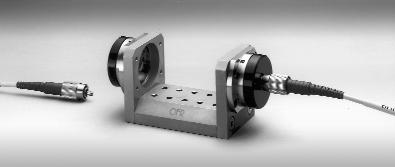
 FiberBench Coupling Systems
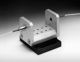
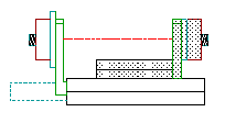
 The Fiber-to-Fiber Coupling System consists of the FiberBench Base with two FiberPorts and two (input
& output) FiberCables (distal end is cleaved). The Fiber-to-Fiber Coupling System is "empty", containing no Optical Component Modules, and is used for coupling light from one fiber to another across an open air-gap.
In all FiberBench Coupling Systems using OFR PM FiberCables, both the slow axis and the FC receptacle keyway are vertical. Both the plane of polarization and the fiber stress rods are vertical.
A major feature of OFR FiberBench Coupling Systems is stability. Transmittance remains constant after temperature change, shock and vibration far greater than experienced in typical laboratory use.
STANDARD WAVELENGTHS (nm)
633 780 850 1310
670 810 980 1550
690 830 1064
|
|
Disconnectable Fiber Couplers
Alignment Instructions
All FFB -X series Fiber-Fiber couplers are OFR aligned to the included input and output fiber cables. Default input/output fibers are 1m in length and do not include fiber connectors on the distal ends of the fiber. Connectors can be added to the distal ends. The input and output fiber cables can be removed and reattached without affecting overall insertion loss. If you change fiber cables from the OFR provided ones the Fiber-Fiber coupler may not maintain alignment. Please contact OFR to inquire about realigning.
Disconnectable
Fiber-Fiber Coupler |
-S
(SM Input/Output) |
-P
(PM Input/Output) |
| Includes: |
-
FB-38 Bench
-
x2 PAF FiberPorts
-
x2 Fiber cables
-
OFR Alignment
|
|
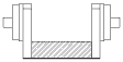
FFBS-S-λ-X
Short Base
IL:
1310 & 1550nm: 0.6dB ± 0.3dB
633, 780, 850, 1064: 0.85dB ± 0.3dB
|
FFBS-P-λ-X
Short Base
IL:
1310 & 1550nm: 0.6dB ± 0.3dB
633, 780, 850, 1064: 0.85dB ± 0.3dB |
| Includes: |
-
FB-51 Bench
-
x2 PAF FiberPorts
-
x2 Fiber cables
-
OFR Alignment
|
|
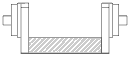
FFBM-S-λ-X
Medium Base
IL:
1310 & 1550nm: 0.6dB ± 0.3dB
633, 780, 850, 1064: 0.85dB ± 0.3dB
|
FFBM-P-λ-X
Medium Base
IL:
1310 & 1550nm: 0.6dB ± 0.3dB
633, 780, 850, 1064: 0.85dB ± 0.3dB |
| Includes: |
-
FB-76 Bench
-
x2 PAF FiberPorts
-
x2 Fiber cables
-
OFR Alignment
|
|
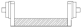
FFBL-S-λ-X
Long Base
IL:
1310 & 1550nm: 0.6dB ± 0.3dB
633, 780, 850, 1064: 0.85dB ± 0.3dB
|
FFBL-P-λ-X
Long Base
IL:
1310 & 1550nm: 0.6dB ± 0.3dB
633, 780, 850, 1064: 0.85dB ± 0.3dB |
Permanent Pigtailed Fiber Couplers
All FFB -Y series Fiber-Fiber couplers are aligned with permanently attached input and output fibers. Default input/output fibers are 1m in length and do not include fiber connectors. Connectors can be added to the distal ends. The -Y versions are ideal for production environments where you want to make certain that users can not chage the alignment of the system. Coupling into and out of the coupler can be accomplished by either using FC mating collers with connectorized fibers or by fusion splicing to the FiberBench.
Permanent Pigtailed
Fiber-Fiber Coupler |
-S
(SM Input/Output) |
-P
(PM Input/Output) |
|
FFBS-S-λ-Y
Short Base
IL:
1310 & 1550nm: 0.6dB ± 0.3dB
633, 780, 850, 1064: 0.85dB ± 0.3dB
|
FFBS-P-λ-Y
Short Base
IL:
1310 & 1550nm: 0.6dB ± 0.3dB
633, 780, 850, 1064: 0.85dB ± 0.3dB |
|
FFBM-S-λ-Y
Medium Base
IL:
1310 & 1550nm: 0.6dB ± 0.3dB
633, 780, 850, 1064: 0.85dB ± 0.3dB
|
FFBM-P-λ-Y
Medium Base
IL:
1310 & 1550nm: 0.6dB ± 0.3dB
633, 780, 850, 1064: 0.85dB ± 0.3dB |
|
FFBL-S-λ-Y
Long Base
IL:
1310 & 1550nm: 0.6dB ± 0.3dB
633, 780, 850, 1064: 0.85dB ± 0.3dB
|
FFBL-P-λ-Y
Long Base
IL:
1310 & 1550nm: 0.6dB ± 0.3dB
633, 780, 850, 1064: 0.85dB ± 0.3dB |
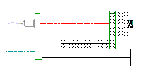
Variable Delay Lines
Variable Delay Lines
A Variable Delay Line is a modified FiberBench that is actually a stainless steel precision translation stage on which are mounted two FiberPorts. Used in applications requiring a variable optical path length, the VDL Variable Delay Line has a precision z-axis translation slide with micrometer actuator. With the VDL it is possible to control with high resolution the air-path length of the collimated beam between the FiberPorts. In order that the system retain the inherent stability of all FiberBenches, the OFR VDL Variable Delay Line is designed to eliminate backlash and cross-talk between axes, and to repeat within 1 µm (~3.3 f-s) anywhere over its travel range. |
|
Part
Number |
Air Gap
Change |
Total
Delay (ps) |
Fiber
In/Out |
Insertion
Loss |
| |
|
|
|
1310, 1550 nm |
633 - 1064 nm |
| VDL-FFB-25-P-λ-X or X/Y |
25 mm |
0 - 83ps |
PM |
0.5 - 1.5 dB |
0.8 - 1.8 dB |
| VDL-FFB-25-S-λ-X or X/Y |
25 mm |
0 - 83ps |
SM |
0.5 - 1.5 dB |
0.8 - 1.8 dB |
| VDL-FFB-13-P-λ-X or X/Y |
13 mm |
0 - 43ps |
PM |
0.5 - 1.5 dB |
0.8 - 1.8 dB |
| VDL-FFB-13-S-λ-X or X/Y |
13 mm |
0 - 43ps |
SM |
0.5 - 1.5 dB |
0.8 - 1.8 dB |
Note: 1 µm ≈3.3 p-s delay
When ordering, specify options as follows:
λ: Wavelength in nm
X: Connector Interface (FC/APC)
X/Y: Permanent Pigtail one end, connector other end
For example VDL-FFB-13-S-1550-X
Dimensions subject to change without notice, |
Variable Delay Line |
-S
(SM Input/Output) |
-P
(PM Input/Output) |
Includes:
-
VDL-13
-
x2 Fiber cables
-
OFR Alignment
|
VDL-FFB-13-S-λ-X
Adjustment range: 0 - 13 mm
Delay: 0 - 43 pico seconds
|
VDL-FFB-13-P-λ-X
Adjustment range: 0 - 13 mm
Delay: 0 - 43 pico seconds |
|
VDL-FFB-13-S-λ-X/Y
Adjustment range: 0 - 13 mm
Delay: 0 - 43 pico seconds
|
VDL-FFB-13-P-λ-X/Y
Adjustment range: 0 - 13 mm
Delay: 0 - 43 pico seconds |
Includes:
-
VDL-25
-
x2 Fiber cables
-
OFR Alignment
|
VDL-FFB-25-S-λ-X
Adjustment range: 0 - 25 mm
Delay: 0 - 83 pico seconds
|
VDL-FFB-25-P-λ-X
Adjustment range: 0 - 25 mm
Delay: 0 - 83 pico seconds |
Includes:
-
VDL-25
-
Permanently attached input disconnectable output
-
OFR Alignment
|
VDL-FFB-25-S-λ-X/Y
Adjustment range: 0 - 25 mm
Delay: 0 - 83 pico seconds
|
VDL-FFB-25-P-λ-X/Y
Adjustment range: 0 - 25 mm
Delay: 0 - 83 pico seconds |
|


