| Introduction
FB-PAM, the OFR FiberBench Polarization Analyzer, is a highly accurate, intuitive, and easy-to-use manual polarimeter. The System completely describes the State of Polarization (SOP) of light, whether from an optical fiber, or from a free-space beam.
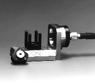
The FB-PAM consists of a Fiber
Bench Collimator System on which is mounted a Module Capture Cage with State of Polarization (SOP) Module. Included are analysis software, applications notes and operations manual.
Description
The FB-PAM uses time-sequential polarimetry, the most fundamental method of polarization measurement. Here, four required intensities are measured in sequence.
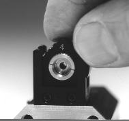
The heart of the FB-PAM is the SOP Module, a triangular block in which are mounted a Polarizer and a 1/4-Wave Retarder. The Module is set into its Capture Cage which is mounted on the FiberBench base plate. The Module is inserted into the beam path, and the four intensity values are measured. These numeric values are entered into the supplied analysis software, which calculates and displays complete polarimetric information in graphical and tabular form.
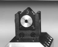
The accuracy of the FB-PAM is ensured by the tight manufacturing tolerances of the SOP Module. It is a precision machined 45°-45°-90° triangle, the simplest of geometric shapes. Measurements are made with the Module in each of three positions, corresponding to the three faces of the triangle. The design eliminates human error. |
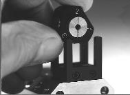
An added safety feature of the Module Capture Cage is that it does not allow the SOP Module to tilt during installation/removal, thus eliminating any chance of stray reflections from optical surfaces.
Finally, all optical surfaces are deeply recessed in the Module, thus preventing inadvertent fingerprints on optical apertures.
Operation
In order to analyze the SOP of light, the FB-PAM requires a collimated beam. Normally, the light-under-test is from an optical fiber. This fiber
is connected to the FiberPort Collimator. From this, a collimated beam transmits through the optical components in the SOP Module and directly to a detector or power meter.
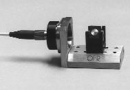
The FB-PAM can be bolted directly to the optical table, or it can be post-mounted to simplify alignment. Any detector or power meter can be used to measure the transmitted intensity.
A high strength magnet is imbedded in the Cage Base, and a magnetic disc is imbedded in each of the three facets of the SOP Module. When the Module is set in any of its three positions, the Cage Base magnet grabs against the corresponding magnetic disc in the SOP Module. This force of attraction, in combination with tight-tolerance machining, assures absolutely repeatable positioning, time-after-time, as the Module is set in sequence in the Cage.
 |
The Sequence of Measurements is as follows.
Measurement #1
Tthe SOP Module is reset in the Cage so that the engraved '1' is at the top position, facing the beam. In this position, the horizontal, linearly polarized portion of the light-under-test is measured. The value on the power meter is entered into the appropriate box in the software.
Measurement #2
The SOP Module is reset in the Cage with the engraved '2' at the top position. The vertical, linearly polarized portion of the light-under-test is measured. The value is entered.
Measurement #3
The SOP Module is reset with the engraved '3' at the top position. The 45°, linearly polarized portion of the light-under-test is measured. The value on the power meter is entered.
Measurement #4
During the previous three measurements, the engraved #4 has faced away from the input beam. Now, it is necessary to turn the SOP Module "backwards" so that the #4 faces forward, and is at the top. In this position, the right-circularly polarized portion of the light-under-test is measured. The value is entered. |
