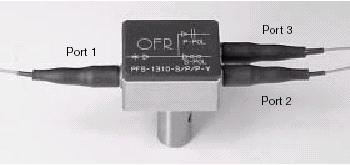
OFR Polarization Splitters divide the input (Port 1) into two oppositely polarized outputs (Ports 2 and 3).
The standard P/P/P model equally splits the input energy into the two outputs.
OFR Polarization Combiners do the reverse of the Splitters. Two oppositely polarized inputs (Port 2 and 3) are combined into a single output (Port 1). In the P/P/P model, the combined energies are coupled into both slow and fast axes of the output fiber (Port 1).
OFR Walk-OFF Polarizers in OFR Splitters separate the two polarization modes better than 55 dB. Because of near-zero absorption and absence of any optical cement, Walk-Off Polarizers are capable of handling very high powers, far beyond those in a fiber-optic system. Walk-Off Polarizers are inherently extremely broadband. AR coated, specify l .
The PM Fibers (PANDA) on all models are aligned so that the plane of polarization is parallel to the slow axis in the fiber.
1-Meter Fiber pigtails on all models can be ordered as single-mode (SM) or polarization-maintaining (PM), as designated in the Part Number. Distal end is cleaved or optionally connectorized.
Polarization Splitters |
Input on Port 1, and oppositely polarized outputs on
Ports 2 and 3. Pigtails can be ordered as Single-mode (S)
or Polarization Maintaining (P) on all Ports.
|
Catalog Number |
Description |
Comments |
PFS-λ-S/P/P |
Standard Splitter |
Cement-free |
PFS-λ-S/S/S |
Standard Splitter |
Cement-free |
PFS-λ-P/P/P |
Standard Splitter |
Cement-free |
| NOTE: when ordering, specify λ in nm. |
Polarization Combiners |
Oppositely polarized inputs on Ports 2 and 3. Output on
Port 1. Pigtails can be ordered as Single-mode (S) or
Polarization Maintaining (P) on Port 1. Polarization
Maintaining (P) only on Ports 2 and 3.
|
Catalog Number |
Description |
Comments |
PFC-λ-P/P/S |
Combiner |
Cement-free |
PFC-λ-P/P/P |
Combiner |
Cement-free |
| NOTE: when ordering, specify λ in nm. |
| Specifications |
|
| Total Insertion Loss |
0.5-1.2 dB |
| Extinction Ratio (on PM output) |
25-32 dB |
| Return Loss (back reflection) |
50-65 dB |
| PM Fiber |
Panda PM |
| Operating Temperature |
0°C to 40°C |
| Storage Temperature |
-20°C to 60°C |

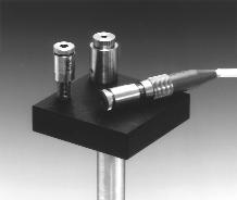
In-Line Polarizer with SOP* Monitor Output
Based on the OFR Polarization Splitter design (see page FO-49), the In-Line Polarizer contains a crystal polarizer (see page FO-14) that separates light into its S and P components by >55 dB. Assuming the input is predominately S-polarized, with some P-polarized component included, the In-Line Polarizer passes pure S-pol straight through and out from Port 2. Any P-pol content is split off and outputs from Port 3.
-
Fiber extinction measurement
- Clean-up polarizer
- System monitoring of linear
polarized light
- Feedback source for active
- polarization control
- Polarization analysis
|
|
Clean-Up Polarizer
The slow axis of the input PM fiber at Port 1 is aligned to the polarizing axis of the crystal so that only correctly aligned S-pol can pass through to output Port 2. Any P-pol component is split off and directed to Port 3, the monitor output. Thus, the In-Line Polarizer "cleans up" degraded extinction ratio in a PM fiber by removing the P-pol component and passing only the S-pol.
SOP Monitor, Port 3
Because any P-polarized component in the input is split off and is output from Port 3, that output can be used to monitor any change in SOP of the input PM fiber. For information on polarization analysis, see page FO-3
Definitions
Port 3 Signal (total P-pol component in the input) = Port 3 Output - Polarization Noise (inherent leakage of S-pol into Port 3 Output).
Thus, Polarization Noise limits the minimum detectable departure of the input from "perfect" SOP.
Extinction Ratio Resolution is the ratio of Port 3 Signal ÷ Port 2 Signal, where Port 2 Signal is the S-pol content in the input. This indicates the minimum detectable "undesirable" polarization.
| Specifications |
(1 - 2) |
(1-3) |
Insertion Loss
|
0.4 - 0.9 dB |
0.5 - 1.1 dB |
Extinction (output from PM at Port 2)
|
> 27 dB |
Return Loss (1-2)
|
> 50 dB |
PM Fiber
|
PANDA |
*The slow axis of the input PM fiber at Port 1 is aligned to the polarizing axis of the crystal so that only correctly aligned S-pol can pass through to output Port 2. Any non S-Pol component is split off and directed to Port 3, the monitor output. Thus, the In-Line Polarizer "cleans up" degraded extinction ratio in a PM fiber by removing the non linearly component which transmits to Port 3. |
Catalog
Number
|
Description |
| PFP-λ-P/P/P |
In-Line Polarizer with |
| |
|
Add-On Polarizers
Stainless Steel Add-On Polarizers
are designed to slip onto a Snap-On Collimator (page FO-45), to polarize the collimated beam output.
Linear Polarizer
AR coated, dichroic thin-plate Polarizer, > 45 dB (3 x 10⁻⁴), > 98%
transmittance, in Rotating Mount.
Applications:
- clean-up polarizer
- measuring extinction of PM fiber
Extinction measurement of PM fiber could not be easier. First, turn the Add-On Polarizer to maximum output from the PM FiberCable and measure that value. Then, turn the Polarizer to minimum output and measure that. The ratio is the extinction.
The Add-On Polarizer slips onto the Snap-On Collimator, and locks in place after the desired plane-of-polarization orientation has been set. A unique magnetic coupling enables this adjustment without danger of drifting.
|