In-Line Polarizer with SOP* Monitor Output
Based on the OFR Polarization Splitter design (see page FO-49), the In-Line Polarizer contains a crystal polarizer (see page FO-14) that separates light into its S and P components by >55 dB. Assuming the input is predominately S-polarized, with some P-polarized component included, the In-Line Polarizer passes pure S-pol straight through and out from Port 2. Any P-pol content is split off and outputs from Port 3.
-
Fiber extinction measurement
- Clean-up polarizer
- System monitoring of linear
polarized light
- Feedback source for active
- polarization control
- Polarization analysis
|
|
Clean-Up Polarizer
The slow axis of the input PM fiber at Port 1 is aligned to the polarizing axis of the crystal so that only correctly aligned S-pol can pass through to output Port 2. Any P-pol component is split off and directed to Port 3, the monitor output. Thus, the In-Line Polarizer "cleans up" degraded extinction ratio in a PM fiber by removing the P-pol component and passing only the S-pol.
SOP Monitor, Port 3
Because any P-polarized component in the input is split off and is output from Port 3, that output can be used to monitor any change in SOP of the input PM fiber. For information on polarization analysis, see page FO-3
Definitions
Port 3 Signal (total P-pol component in the input) = Port 3 Output - Polarization Noise (inherent leakage of S-pol into Port 3 Output).
Thus, Polarization Noise limits the minimum detectable departure of the input from "perfect" SOP.
Extinction Ratio Resolution is the ratio of Port 3 Signal ÷ Port 2 Signal, where Port 2 Signal is the S-pol content in the input. This indicates the minimum detectable "undesirable" polarization.
| Specifications |
(1 - 2) |
(1-3) |
Insertion Loss
|
0.4 - 0.9 dB |
0.5 - 1.1 dB |
Extinction (output from PM at Port 2)
|
> 27 dB |
Return Loss (1-2)
|
> 50 dB |
PM Fiber
|
PANDA |
*The slow axis of the input PM fiber at Port 1 is aligned to the polarizing axis of the crystal so that only correctly aligned S-pol can pass through to output Port 2. Any non S-Pol component is split off and directed to Port 3, the monitor output. Thus, the In-Line Polarizer "cleans up" degraded extinction ratio in a PM fiber by removing the non linearly component which transmits to Port 3. |
Catalog
Number
|
Description |
| PFP-λ-P/P/P |
In-Line Polarizer with |
| |
|
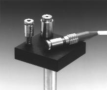
Add-On Polarizers
Stainless Steel Add-On Polarizers
are designed to slip onto a Snap-On Collimator (page FO-45), to polarize the collimated beam output.
Linear Polarizer
AR coated, dichroic thin-plate Polarizer, > 45 dB (3 x 10⁻⁴), > 98%
transmittance, in Rotating Mount.
Applications:
- clean-up polarizer
- measuring extinction of PM fiber
Extinction measurement of PM fiber could not be easier. First, turn the Add-On Polarizer to maximum output from the PM FiberCable and measure that value. Then, turn the Polarizer to minimum output and measure that. The ratio is the extinction.
The Add-On Polarizer slips onto the Snap-On Collimator, and locks in place after the desired plane-of-polarization orientation has been set. A unique magnetic coupling enables this adjustment without danger of drifting.
|