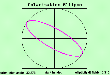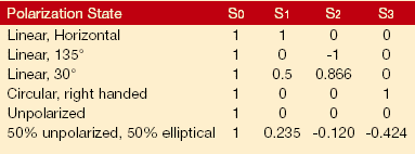

Sample data box generated by analysis spreadsheet
Data analysis
These four intensity measurements are all that is required to calculate all of the polarimetric information about the light-under-test. The software processes the data via matrix multiplication (the exact details of which depend on the Calibration Option selected by the user).
The following quantities are calculated and displayed in the software:
- Stokes Parameters
- Jones Vector
- Degree of Polarization
- Degree of Linear Polarization
- Linear Polarization Extinction
- Azimuth Angle
- Degree of Circular Polarization,
Ellipticity, Helicity (handedness)

Plots of the Degree of Polarization, Stokes Parameters, and Polarization
Ellipse are generated, and can be printed or exported to other applications.
|
In addition, the ExcelT platform allows the user to customize the program and to add calculations, plots, and graphs.

Applications
In addition to measuring the SOP of light-under-test, the FB-PAM can also characterize fiber-pigtailed devices and bulk optics. For example, the FB-PAM can answer the following questions:
- What is the SOP of a signal
(free-beam or fiber-optic)?
- What is the Polarization-Dependent Loss/Gain of a fiber device?
- What is the extinction ratio after propagating through PM or PZ fiber?
- What is the retardance of a retarder?
- Has a signal been depolarized after propagating through a long single mode fiber? Through a multimode fiber?
- Is the SOP changed after propagating through short lengths of
singlemode fiber?
- What are the effects of multilayer coatings on the SOP?
- What are the polarizing effects of a beamsplitter?
- Does a beamsplitter change the phase of the polarization?
- How effective is a depolarizer at reducing degree of polarization?
Theory
The State of Polarization (SOP) of light describes the orientation and oscillation of its electric field. It is uniquely specified by four quantities known as the Stokes Parameters. These Parameters, designated as S0, S1, S2 and S3, are defined as:

Where:
- Ix° refers to the intensity of the light that transmits through a Linear Polarizer oriented at x°.
- IRCP and ILCP are the intensities transmitted through a right-hand and left-hand circular polarizer, respectively.
- S0 is the total intensity of the light.
- S1 represents the dominance of horizontally polarized light vs. vertically-polarized light.
- S2 represents the dominance of 45° polarized light vs. 135° polarized light.
- S3 represents the dominance of right-circular polarization vs. left-circular polarization.

Although six intensity values are required to define the Stokes Parameters, a fundamental relationship allows the four measurements: I0° + I90° = I45° + I135° = IRCP + ILCP.
When the Stokes Parameters are known, the SOP can be completely described. It is a remarkable result that the electric field can be determined solely by these intensity values.
|
|

![]()