Purpose of an Isolator OFR isolators are used to reduce or eliminate
the effects of optical feedback...reflections of the laser's own
energy back into itself. The effects of optical feedback are well
known: amplitude fluctuation, frequency shift, limitation of modulation
bandwidth, noise and even damage.
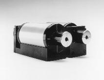
Much like a diode in an electrical circuit, the isolator
transmits light in one direction only. An isolator consists of a
Faraday rotator, two polarizers and a body to house the parts. The
Faraday rotator consists of a magneto-optic material contained in
a magnetic field.
The Faraday Effect In 1842, Michael Faraday discovered that
the plane of polarized light rotates while transmitting through
glass (or other material) that is contained in a magnetic field.
The direction of rotation is dependent on the direction of the magnetic
field, and not on the direction of light propagation (non-reciprocal).
The amount of rotation, Q, equals VLH, where: V is the Verdet Constant,
a property of the optical material, in minutes/Oersted-cm.
L is the path length through the optical material
in cm.
H is the magnetic field strength in Oersted.
It is important to note that the Verdet Constant
is wavelength-dependent.
OPERATION OF AN ISOLATOR
The forward mode Laser light, whether or not polarized,
enters the Input Polarizer and becomes linearly polarized, say in
the vertical plane (0°). It then enters the Faraday rotator
rod, designed to rotate the plane of polarization (POP) by 45°,
say in the ccw sense. It then exits through the Output Polarizer
whose axis is at 45°. The light leaves the Isolator, and reflections
occur. This reflected light constitutes feedback.
The reverse mode This feedback re-enters the Isolator,
back through the Output Polarizer where it is repolarized at 45°.
It then passes back through the rotator rod and is further rotated
by another 45°, still in the ccw sense, making a total of 90°
with respect to the Input Polarizer (0°). It is seen that the
light is extinguished here. Thus, we have succeeded in isolating
the laser from its own reflections.
Horizontal or Vertical
Polarization? Unless otherwise specified at time of
order, OFR Isolators are set for horizontal input polarization.
However, most models can be easily reset for vertical input merely
by rotating each polarizer 90°.
Whether horizontal or vertical input, the output plane
of polarization will be at 45°, the specific quadrant depending
upon the model.
An alternate means of rotating the output is the Polarization
Rotator (1/2-Wave Retarder), mounted on the Output Poarizer.
In a correctly adjusted isolator, maximum isolation
and transmission occur together when the axis of the Input Polarizer
is parallel to the plane of the polarized laser, and the Output
Polarizer is at 45°. If the wavelength changes, then rotation
is no longer 45°, and both isolation and transmission will decrease.
Thus, it is desirable to readjust the isolator if the wavelength
changes.