INTRODUCTION
Figure 1 shows a TE LaserPort on a FiberBench. The large black module on the back of the FiberBench wall is the heat sink. The stainless steel assembly on the inside of the Fiber Bench wall is the LensPort. The LensPort contains a movable lens and collimates the light coming out of the laser diode. |
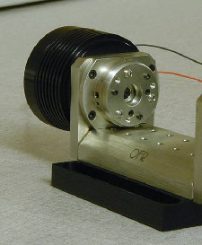
Fig.1 TE LaserPort on a FiberBench.
|
INSTALLATION OF THE DIODE
- Remove any modules from the FiberBench.
- Remove the FiberPort from the inside wall by removing the four socket head screws with a 5/64 hex wrench (Figure 2). If applicable, remove the LensPort and isolator module from the opposite wall. Set aside.
- Remove the three flat head screws from the back of the heat sink using a 1/16 hex wrench. If a wiring strain relief cap is installed, the whole assembly will come out together as one piece. Otherwise the black cover will come alone as shown (Figure 3).
- Remove the black wave washer that sits between the cap and the copper assembly.
|
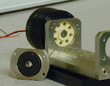
Fig.2 TE LaserPort with LensPort removed. View with diode installed.
LaserPort on a FiberBench.

Fig.3 Removing the black cover from the TE LaserPort.
|
- Gently push the copper assembly out of the heat sink (Figure 4), including the off-white ceramic insulator which can be seen in Figure 2.
|
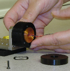 Fig.4 Removing the assembly.
|
- Insert diode in laser socket on the copper seat (Figure 5).
|
 Fig.5 Diode placed on copper seat.
|
- Place the ceramic insulating seat on top of the copper assembly and reinsert into the heat sink (Figure 6). The ceramic component will seat into the FiberBench wall (Figure 7).
|
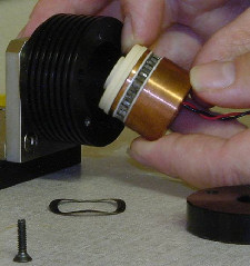 Fig.6 Inserting the copper assembly with the ceramic seat into the heat sink.
|
- Reassemble the LaserPort. Replace the wave washer, the end cap, and the three flat head screws.
- Replace the LensPort on the inside of the FiberBench wall using the four socket head screws. Ensure that the X-Y adjustment screws are accessible. The Y adjustment screw is on the outer diameter of the LensPort in the 12 o’clock position.
- Connect the laser diode to the power supply and the TE cooler as recommended by the laser and cooler manufacturer.
- Refer to the FiberPort alignment instructions in collimating the light out of the laser diode.
|
 Fig.7 The ceramic seat seated into the FiberBench wall with properly installed diode.
 |
